Overview of pinouts
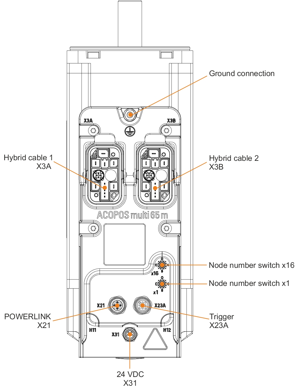
X21 (POWERLINK)
X21 (POWERLINK)
Figure | Pin | Description | Function |
|---|---|---|---|
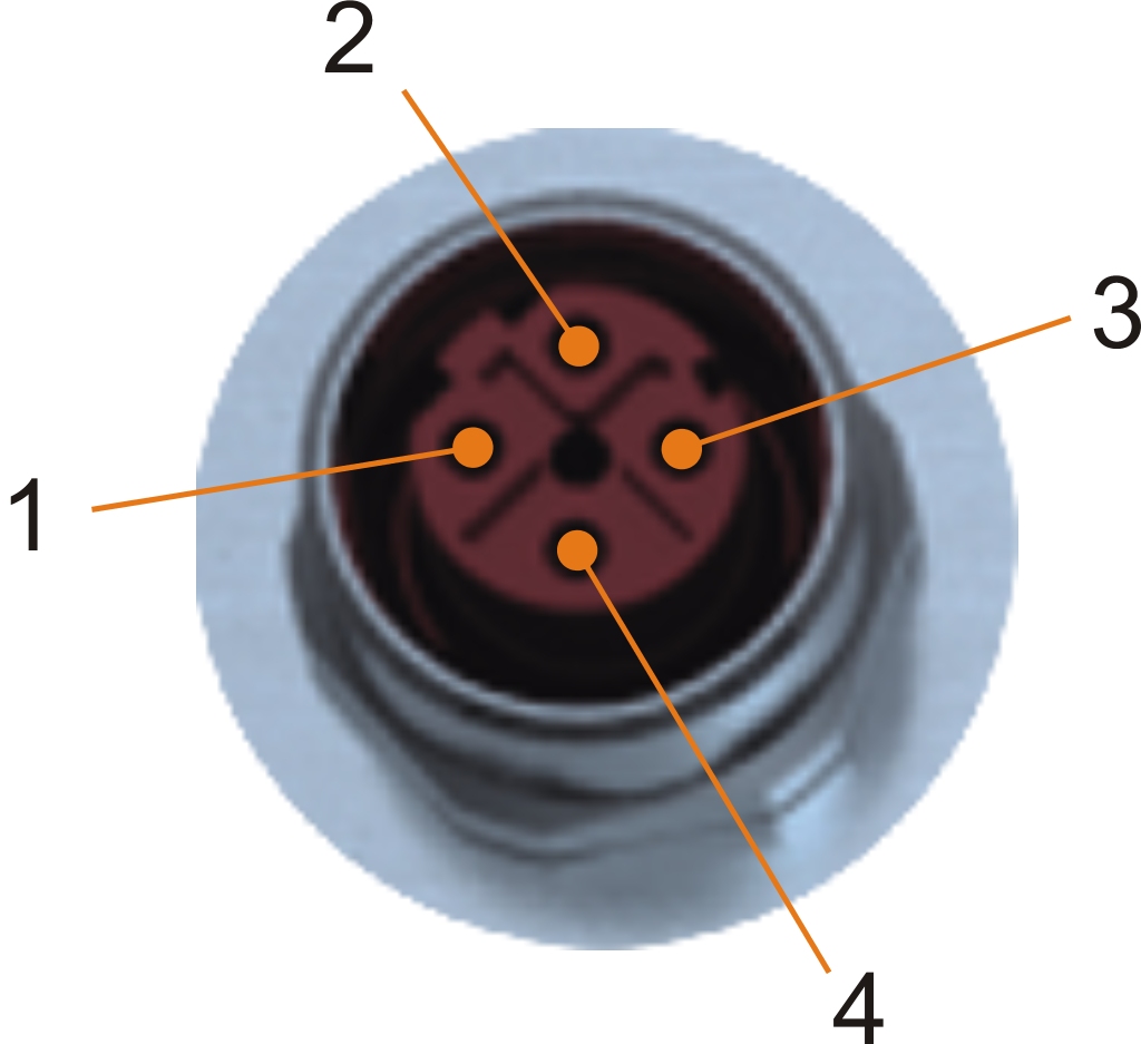 | 1 | TXD | Transmit data |
2 | RXD | Receive data | |
3 | TXD\ | Transmit data inverted | |
4 | RXD\ | Receive data inverted |
X23A (Trigger)
X23A (Trigger)
Figure | Pin | Description | Function |
|---|---|---|---|
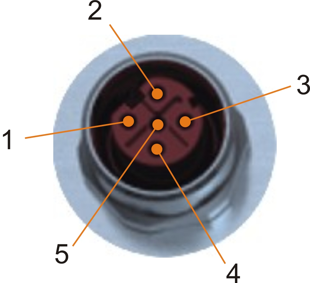 | 1 | +24 V | Sensor/actuator power supply 24 VDC 1) |
2 | Trigger1 | Trigger input 1 | |
3 | GND | GND | |
4 | Trigger2 | Trigger input 2 | |
5 | --- | --- |
| 1) | Sensors/Actuators are not permitted to be supplied externally. |
X31 (24 VDC routing)
X31 (24 VDC routing)
Figure | Pin | Description | Function |
|---|---|---|---|
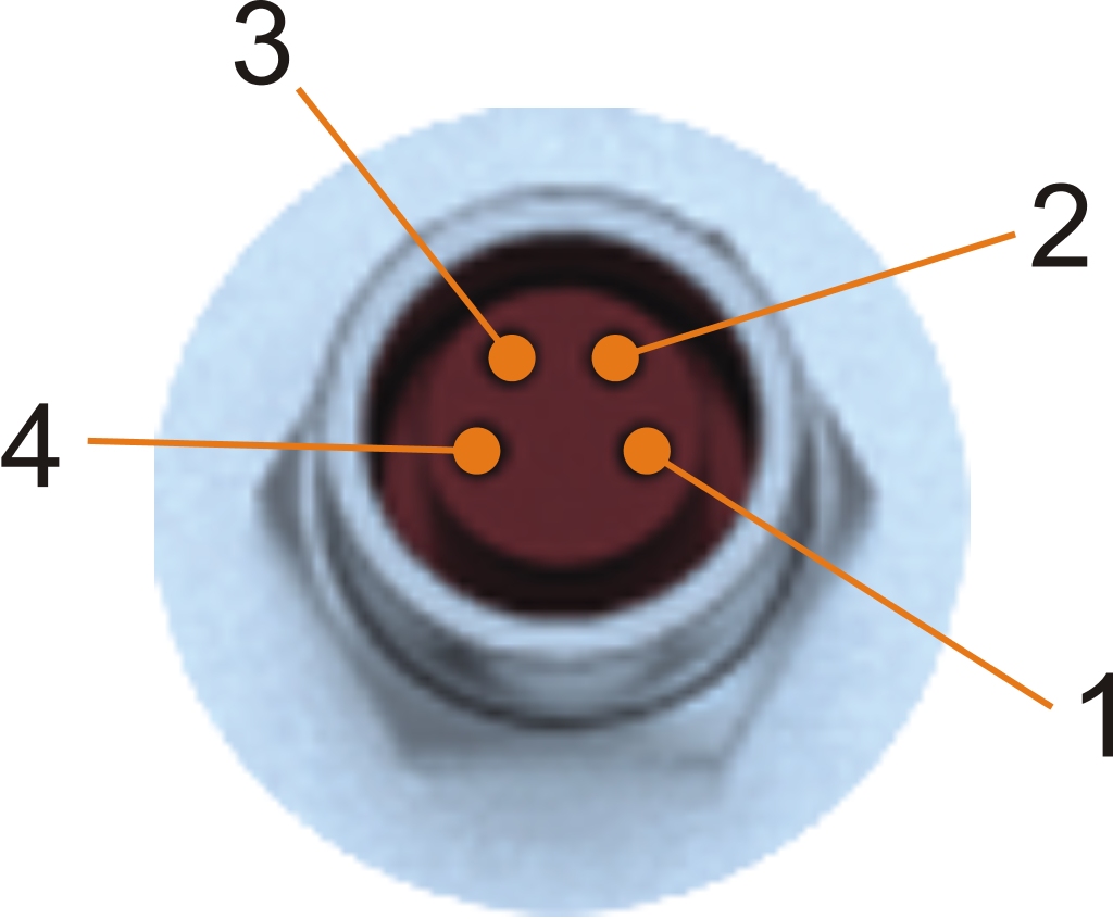 | 1 | 24 VDC I/O | 24 VDC I/O power supply |
2 | 24 VDC I/O | 24 VDC I/O power supply | |
3 | GND | 24 VDC I/O power supply 0 V | |
4 | GND | 24 VDC I/O power supply 0 V |
Ground connection (PE)
Ground connection (PE)
The protective ground conductor is connected to the M5 threaded bolt provided using a cable lug.
Figure | Pin | Name | Function |
|---|---|---|---|
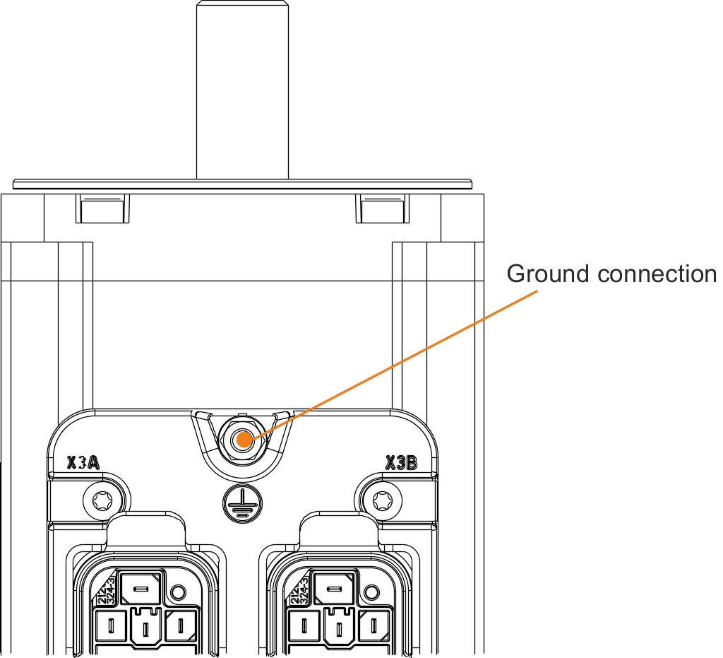 | --- | PE | Protective ground conductor |
Terminal cross sections | [mm²] | AWG | |
Cable lug for M5 threaded bolt | 0.25 - 16 | 23 - 5 | |